| Prev | ICM User's Guide 22.7 Homology Modeling and Structure Analysis Tools | Next |
[ Homology Modeling | Linked Alignments and Structure | Mutation | Health | Superimpose ]
Overview
This lesson will take you through the basics of protein modeling. Topics include:
- Building a homology model.
- Linked alignments and structures.
- Protein health and regularization.
- Protein folding and structure prediction.
Background
ICM has an excellent record in building accurate models by homology. The ICM modeling procedure builds the framework, shakes up the side-chains and loops by global energy optimization. You can also color the model by local reliability to identify the potentially wrong parts of the model. ICM also offers a fast and completely automated method to build a model by homology and extract the best fitting loops from a database of all known loops. It just takes a few seconds to build a complete model by homology with loops. Some selected publications related to modeling and structure determination are listed here.
Abagyan, R.A., and Totrov, M.M. (1994). Biased Probability Monte Carlo Conformational Searches and Electrostatic Calculations for Peptides and Proteins. J. Mol. Biol., 235, 983-1002
Cardozo, T., Totrov, M., and Abagyan, R. (1995). Homology modeling by the ICM method. Proteins: Structure, Function, Genetics, 23, 403-414
Abagyan, R., and Totrov, M. (1999). Ab initio folding of peptides by the optimal-bias Monte Carlo minimization procedure. Journal of Computational Physics, 151, 402-421
Maiorov, V.N., and Abagyan, R.A. (1997). A new method for modeling large-scale rearrangements of protein domains. Proteins, 27, 410-424
Schapira, M., Totrov, M. and Abagyan, R. (2002). Structural Model of Nicotinic Acetylcholine Receptor Isotypes Bound to cetylcholine and Nicotine. BMC Structural Biology 2:1
ICM also provides powerful tools for determining crystallographic symmetry and neighbors which allows the biological environment of a protein to be viewed and understood.
22.7.1 Homology Modeling |
Objective
To make a protein model based on sequence homology.
Background
ICM has an excellent record in building accurate models by homology. The procedure will build the framework, shake up the side-chains and loops by global energy optimization. You can also color the model by local reliability to identify the potentially wrong parts of the model.
Instructions
- Edit/Delete All . let us begin with a clear ICM session!
- Homology/Load Example
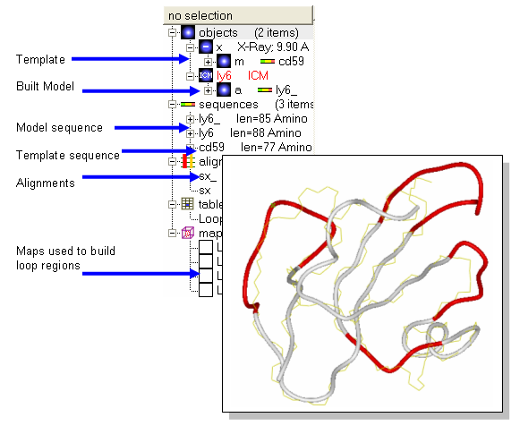
- Two sequences (ly6,CD59), one template structure (x) and an alignment (sx) should be loaded. Sequence CD59 is the sequence of the template structure called x.
- Homology/Build Model and fill in the table using the drop down options. Warning minimize side-chains may take a few minutes.
Notes and things to try:
- The four built in loops are shown in red as default.
- Try displaying the model and the template in different colors or representations to observe any siginificant deviations between template and model.
Manual References (Web Links)
22.7.2 Linked Alignments and Structures |
Objective
To select, display and label the conserved regions of the model.
Background
Within the ICM Alignment Editor there is a rich array of tools. Some of these tools allow selections between a linked alignment and a structure. The strength of consensus can be changed and selections can be made according to a variety of criteria. There will be an alignment symbol next to a structure in the ICM Workspace if the structure is aligned.
Instructions
Using the alignment from the previous lesson we will display and label the conserved residues between our model and the template in CPK format.
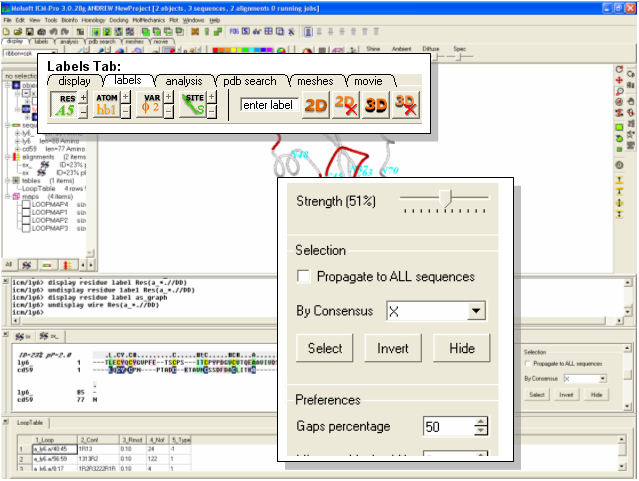
- Change the strength of the alignment consensus to 50% in the ICM Alignment Editor.
- Type in the consensus you wish to select. For example if you only want to select identical residues between the template and model type in X. Other symbols (such as #) from the alignment consensus line can be entered here if desired. You may wish to play with this and the alignment consensus value.
- Click on the Select button and the residues selected will be highlighted with green crosses.
- To label the residues select the display tab and select the label residue button.
Manual References (Web Links)
22.7.3 Making an amino acid mutation |
Background Pim1 is a unique protein kinase because it has a proline residue located in the hinge region which precludes the canonical second hydrogen bond between the hinge backbone and the adenine moiety of ATP. Mutants of Pim1 have been crystallized to see if mutating the proline residue can restore the ATP binding pocketed to that of a typical kinase. As an example we will make a P123M mutation of PIM1.
- Type pdb code 1yxu into the PDB search tab.
- Convert the PDB file into an ICM object.
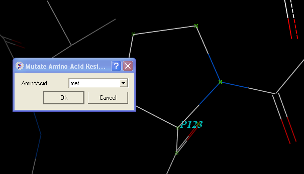
- Select residue number 123 in the "a" subunit
- Right click on the selection in the graphical workspace or ICM workspace and select Advanced/Mutate Amino-Acid
- Select Methionine from the drop down list.
- Now optimize the side chains surrounding the residue.
- Right click on Methionine 123 and select Neigbors/5A > Same Object >include source
- Right click on the selection and choose Advanced/Optimize Side Chains
- The higher the number of calls per variable the longer the simulation. The default number has been shown to provide an ideal simulation length. Press OK.
- MolMechanics/View Stack and look at the solutions ranked by energy by double clicking through the table.
- Compare your mutated structure with the crystal structure of PIM1 with the P123M mutation (PDB code 1yxs)
22.7.4 Protein Health |
Objective
To remove clashes from a PDB structure.
Background
Here we will use a macro that calculates the energy strain (Protein Health) within a protein structure. The macro is based on a paper by Maiorov and Abagyan (1998). The regularization macro will remove any clashes and improve the energy of the structure.
Instructions
- Edit/Delete All . let us begin with a clear ICM session!
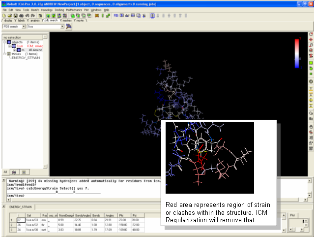
- Search FOR and display the PDB structure 1iva (use PDB search tab).
- Convert 1iva into an ICM object (see previous lesson or search for "convert")
- Tools/3D Predict/Protein Health Note red coloring indicates clashes or high strain. Lets remove these clashes using the ICM regularization tool.
- MolMechanics/Regularization
- Color and display in wire - all clashes should have been removed.
Notes and Things To Try:
- Always use the Protein Health tool and ICM Regularization after you have constructed a protein model.
- It is always wise to check a protein structure from the PDB with the Protein Health tool and then use ICM Regularization to remove any potential problems you may identify.
22.7.5 Superimpose Structures |
[ tut3g ]
Objective
To superimpose two structures.
Background
In this lesson we demonstrate the use of a superposition based upon a sequence alignment. All superposition analyzes can be performed using the button available within the Analyses tab. The example here uses protein kinase structures to superimpose.
Instructions
- File/Open/Example_Alignment.icb
- Read PDB 2PHK
- Extract the sequence from 2PHK and then drag it and drop it into the alignment.
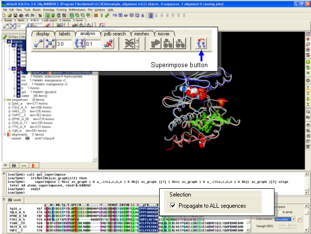
- Select a region of the alignment around which you wish to superimpose. You can use the propogate to all sequences in the Alignment Editor to make this selection.
- Select the display tab and click on the superimpose button.
Notes and Things To Try:
- Try making a superposition around the ligand binding pocket only by selecting the ligand.
- Try improving poorly superimposed regions such as loops.
Manual References (Web Links)
How to Superimpose Two Structures
h3- Protein Folding and Structure Prediction {Folding}
Objective
To use a script to perform protein folding / structure prediction.
Instructions
                     # Example folding script. Use as directed.
 read libraries
 build "pep16"       # your peptide sequence is in pep16.se file.
 rename a_*. "f2"    # specifies current name.
                     # Several runs (f2,f3, etc.) are recommended
 nvar = Nof( v_//* ) # number of variables

 nProc=4             # if you are using parallel version.

 mncallsMC    = nvar*50000  # maximal number of energy evaluations
 mncalls      = 170+nvar*3  # maximal n_of minimization calls after
                            # each random change
 temperature  = 600   # optimal temperature for the simulation
 tolGrad      = 0.01  # exit minimization when gradient is < 0.01
 mcBell       = 1.0   # the default width of the MC probability distributions
 mnconf       = 40    # maximal n_of low-energy conformations saved
                      # in the stack (f2.cnf file)
 mnvisits     = 25    # if stuck for >= 25 times, push it out
 mnreject     = 10
 mnhighEnergy = 30
 l_bpmc       = yes   # use biased probability
 electroMethod = "MIMEL"
 surfaceMethod = "constant tension"
 set terms "vw,14,hb,el,to,sf,en"
                      # ECEPP/2 energy + solvation + entropy (see icm.hdt file)

 fix v_//?vt*         # exclude irrelevant virtual variables specifying
                      # absolute molecular position
 set vrestraint a_/*  # load preferred backbone and side-chain angle zones
                      # for the  biased probability MC
 randomize v_//!omg 180.0  # create random starting conformation
 vicinity = 15.0
 compare v_//phi,psi  # use these variables to compare structure
 montecarlo trajectory # run it and record a trajectory file.
                      # watch the movie later by:
                      # read trajectory "f2"; display ribbon
                      # display trajectory "f2" 4. 8.
                      # analyze the best conf. in the stack by:
                      # build "pep16"; read stack; show stack all
                      # load conf 1
 quit
| Prev Displaying Key Hydrogen Bonds | Home Up | Next Crystallographic Analysis Tools |