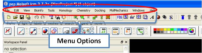
| Prev | ICM User's Guide 3.5 Menu Option Guide | Next |
[ File Menu | Edit Menu | View Menu | Tools Menu - Xray | Tools Menu - 3D Predict | Tools Menu - Analysis | Tools Menu - Superimpose | Tools Menu - Extras | Tools-Menu Table | Tools Menu - Chemical Search | Tools Menu - Molecular Editor | Homology Menu | Chemistry Menu | Docking Menu | MolMechanics Menu | Windows Menu ]
| Note: Click Next (top right hand corner) to navigate through this chapter. Headings are listed on the left hand side (web version) or by clicking the Contents button on the left-hand-side of the help window in the graphical user interface. |
Here we describe all the options in the drop down graphical user interface menus.
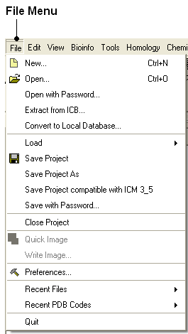
3.5.1 File Menu |
[ New | Open | Open with Password | Extract from ICB | Convert to Local Database | Load | Save Project | Save Project As | Save Compatible | Password | ActiveICM HTML | Close | Quick Image | Write Image | Preferences | Recent Files | Recent PDB Codes | Quit ]
3.5.1.1 New |
[ Peptide | Compound | DNA/RNA | Sequences | Script | HTML | New Table | Box | sphere ]
ICM can read as well as create several different entities. This dialog box helps you to create new entities from scratch:
All the processes in this section can be found under File/New, in the New molecule/sequence/grob window
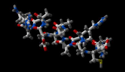
3.5.1.1.1 Constructing a New Peptide |
Creates a peptide as a new ICM Object, named after the string entered in the 'Object name' field. The residue composition of the new peptide is the string entered in the 'One Letter Code' field. The chemical property of the peptide ends will be created according to the type of terminus choosen from the 'N-terminus' and 'C-terminus' drop-down list.
The peptide can be displayed immediately after creation (check the 'Display molecule' option). The new peptide can be folded as an alfa-helix (phi= -62 deg.; psi= -41 deg.), instead of a linear stretch of residues (phi,psi = 180 deg.) (check the 'Assign A-helix' option).
Please note that the created peptide will not be in its most favorable energetic conformation.
To construct a new peptide:
- Select File/New and the New molecule/sequence/grob window will appear.
- Type the peptide sequence into the One letter code data entry box. Remember to delete the previous entry if it is in the box.
| NOTE: If the peptide you wish to make has been made previously then it will be in the drop down menu in the One letter code box. |
- Select the appropriate N-terminal and C-terminal from the drop down menu.
- Check the boxes Display Molecule or Assign A-Helix according to your particular preference.
- Click the OK button.
3.5.1.1.2 Constructing a New Compound |
Creates a compound/ small chemical molecule, based on the SMILES - Simplified Molecular Input Line Entry Specification - string supplied. The name of the compound can be specified on the 'Object name' field. For further information on SMILES syntax http://www.daylight.com/dayhtml/smiles.
The new compound can be displayed immediately after creation (check the 'Display molecule' option). All other objects can be deleted before the creation of the new object (check the 'Delete other objects' option).
Please note that the created compound will not be in its most favorable energetic conformation.
To construct a new compound:
- Select File/New and the New molecule/sequence/grob window will appear.
- Click the Compound tab at the top of the window.
OPTION 1:
- Type in the Smiles String in the Smiles String data entry box. Remember to delete the previous string. If a string has been entered previously it will be available by clicking on the drop-down button.
- Check the boxes Display Molecule or Delete Other Objects according to your preference.
- Click the OK button.
OPTION 2:
- Click the Launch Molecule Editor button.
Please refer to the Molecule Editor section of this manual for instructions.
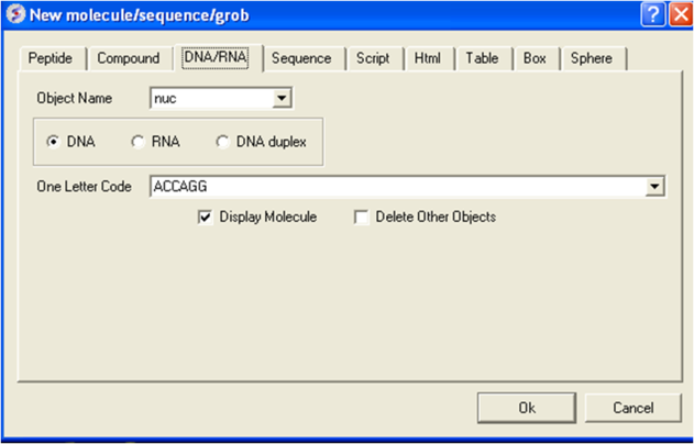
3.5.1.1.3 Constructing New DNA or RNA |
Creates a nucleic acid chain object - either DNA or RNA, according to the selection and the nucleotide sequence. The sequence should be supplied in one-letter code (ATCG) format, starting from 5' end. The name of the DNA/ RNA object can be specified on the 'Object name' field.
If the 'DNA duplex' option is selected, the complementary strand will be created automatically as a separate molecule in the same object.
The new DNA/ RNA can be displayed immediately after creation (check the 'Display molecule' option). All other objects can be deleted before the creation of the new object (check the 'Delete other objects' option).
Please note that the DNA/ RNA will be created as adopting the canonical B-DNA conformation.
To construct new strand of DNA or RNA:
- Select File/New and the New molecule/sequence/grob window will appear.
- Click the Nucleotide tab at the top of the window.
- Check the appropriate box for the nucleotide you are constructing, either DNA RNA or DNA Duplex
- Enter the nucleotide sequence into the One Letter Code data entry box. Remember to delete the previous nucleotide sequence. If a sequence has been entered previously it will be available by clicking on the drop-down button.
- Check the boxes Display Molecule or Delete Other Objects according to your preference.
- Click the OK button.
3.5.1.1.4 Constructing New Protein and Nucleic Acid Sequences |
Creates a new Sequence using the information supplied by the user in FASTA format. The sequence type can be defined as protein or nucleic acid by the user, or automatically detected by ICM. Simply choose one of the options on the dialog box. The sequence name can be specified in the 'Sequence name'.
To construct a new protein and nucleic acid sequence:
- Select File/New and the New molecule/sequence/grob window will appear.
- Click the Sequence tab at the top of the window.
- Copy and paste a Fasta-format sequence into the Sequence data entry box.
- ICM will automatically determine what kind of sequence you have constructed but if you wish to specify then you can check either the protein or nucleic acid box.
- Click the OK button.
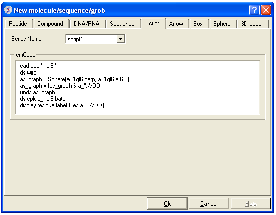
3.5.1.1.5 Writing a Script in GUI. |
Creates a clickable link on the workspace that launches scripts written using ICM language. The link is named after the 'Script Name'.
There are two ways of defining the script to be associated with the link. The first is to input the ICM script directly into the 'IcmCode' field. Alternatively, a file containing an ICM macro can also be associated with the link.
To write a script in the graphical user interface:
- Select File/New and the New molecule/sequence/grob window will be displayed.
- Click the Script tab at the top of the window.
- Write your ICM script in the text box provided (see below) and click OK.
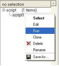
To run or edit your script:
- Right click on the script name in the ICM workspace.
| NOTE: For more details regarding the ICM scripting language please see the separate ICM language manual. |
3.5.1.1.6 HTML |
- File/New HTML tab provides a window to enter HTML code. This window is a good starting point for generating new molecular documents.
3.5.1.1.7 New Table |
To generate a new empty table:
- File/New and select the Table tab and a window as shown below will be displayed.
- Enter the number of rows and columns you wish to include in your table and whether you wish to add a column with chemical data.
3.5.1.1.8 Box |
Creates a 3D box as a new graphical object ('grob' or 'mesh'). This box can be generated both as a solid object or as a simpler wire representation. The name of the box can be defined in the 'BoxName' field.
Dimensions of the box (X, Y, Z) are given in Angstroms and the angles connecting the sides are given in degrees. Color can be assigned by simply clicking on the desired one or using rgb scale (eg. for red: rgb={1. 0. 0.}).
Tip: the box can be moved independently using 'connect'
3.5.1.1.9 sphere |
Creates a 3D sphere as a new graphical object ('grob' or 'mesh'). This sphere can be generated both as a solid object or as a simpler wire representation. The name of the sphere can be defined in the 'BoxName' field.
Dimensions of the sphere (X, Y, Z) are given in Angstroms and the angles connecting the sides are given in degrees. Color can be assigned by simply clicking on the desired one or using rgb scale (eg. for red: rgb={1. 0. 0.}).
Tip: the arrow can be moved independently using 'connect'
3.5.1.2 Open |
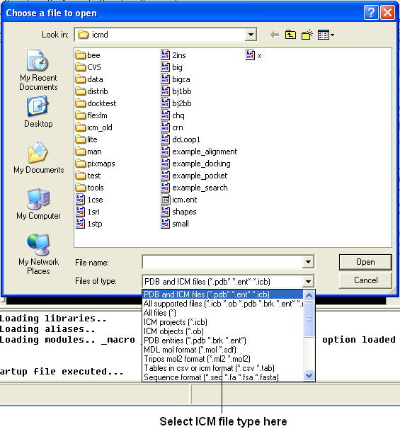
Any file that ICM can understand can be opened by:
- Selecting File/Open.
3.5.1.3 Open with Password |
To open a file that is password protected:
- File/Open with Password
3.5.1.4 Extract from ICB |
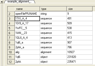
An icb file is an icm project file and this option allows you to view a tabulated list of what the icb file contains.
- File/ Extract from ICB
- Locate the saved icb file.
- A table as shown below will be displayed
- Double-click on any of the entry to extract that item from ICB
3.5.1.5 Convert to Local Database |
Please see the Local Databases chapter for more information about this option.
3.5.1.6 Load |
Options contained within the menu File/Load
PDB - read PDB from FTP, http, and local PDB
From Multiple Object File - A multiple object file will have a file extension *.ob and you can select which member of the multiple object is displayed.
PFam Alignment - PFam is a collection of multiple sequence alignments - enter FASTA ID
SwissProt - Download SwissProt sequence.
All Images from Dir - Read into ICM multiple image files png or jpg.
Electron Density Map - Download electron density map from Uppsala electron density server http://eds.bmc.uu.se/eds/
3D Mesh in KMZ or COLLADA Format from Google - see http://sketchup.google.com/3dwarehouse/ to download KMZ or COLLADA.
3.5.1.7 Save Project |
Saving a project will allow you to quit from ICM and then return to the exact set-up and display at which you left off at a later date. The projects are saved in files with the extension *.icb
To save a project:
- Select File/Save Project and a data entry window will be displayed. This window will only appear if this is the first time you have saved a project.
- Enter the unique name you wish to call your project in the box labeled File name:
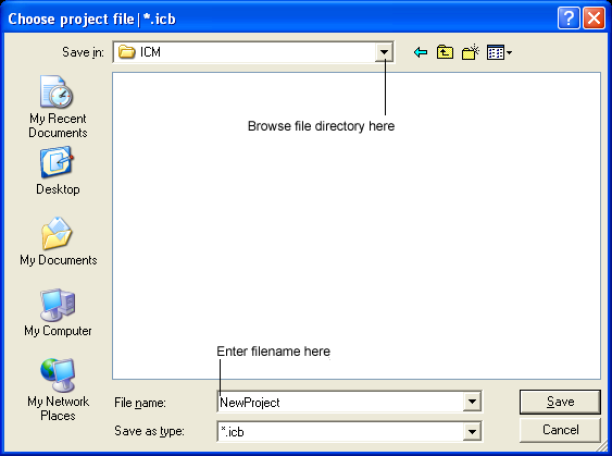
- Choose which folder or directory you wish to save your project in by scrolling down in the box labeled Save in:
- Once the appropriate information has been entered click on the Save button in the bottom right hand section of the window.
- The project is now saved as yourfilename.icb.
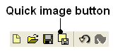
| NOTE: An alternative way to save a project is to click on the save icon on the toolbar. |
![]()
3.5.1.8 Save Project As |
[ Reload/Saved | Reload/NoRun ]
If you wish to re-name the project or save different versions of the same project use the Save Project As option.
To rename a project:
- Click on the File/Save Project option and a data entry window will be displayed. This window will only appear if this is the first time you have saved a project.
- Enter the unique name you wish to call your project in the box labeled File name:
- Choose which folder or directory you wish to save your project by scrolling down in the box labeled Save in:
- Once the appropriate information has been entered click on the Save button in the bottom right hand section of the window.
- The project is now saved as yourfilename.icb.
3.5.1.8.1 Reloading a Saved ICM Object when ICM is Running |
Once an ICM object has been saved you can re-read it by:
- Click on File/Open and a data entry window will be displayed (below).
- Locate your saved ICM Object by clicking on the Browse button in the bottom right hand section of the window.
| NOTE: To make your search easier you can limit the number of files you search through by scrolling down in the Open as section and selecting the appropriate file ending. |
- Click on the OK button when the file has been located and your saved ICM Object will load.
| NOTE: If the file you wish to load has been viewed recently then it will be in the drop down menu in the Open box. |
3.5.1.8.2 Reloading a Saved ICM Object in Windows when ICM is not Running |
To reload a saved project in Windows simply find the file in the "My Computer" file store and double-click on the icon.
3.5.1.9 Save Project Compatible with ICM 3_5 |
File/Save Project Compatible with ICM 3_5
Use this option to save a version of your ICM project compatible with an older version of ICM. Version 3.5 or older. If you have an ICM license you can update your version of ICM by visiting our support site at www.molsft.com/support
3.5.1.10 Save with Password |
To save a project which is protected by a password:
- File/Save with Password
- Enter a file name or browse for a previously saved project.
- Enter a password
- Determine whether you want the file to be Fully Protected, read only or Read Only and Allow Comments .
3.5.1.11 Export as ActiceICM Html |
To embed in a web browser.
- Download ActiveICM from here http://www.molsoft.com/getbrowser.cgi?product=activeicm&act=list (it is free!).
- Create an HTML page in ICM (File/New/Html).
- Add a series of slides.
- File/Export As ActiveICM Html..
3.5.1.12 Close Project |
To close a project:
File/Close Project
3.5.1.13 Quick Image |
A quick image can be saved using this option. The image will be saved as icm1.png in the current directory in which you are working. Each subsequent image produced will be incrementally numbered.
This option is also available via a button as shown below:
3.5.1.14 Write Image |
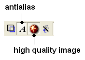
Before saving an image it is best to improve the quality of the image using the "High Quality Image" and antialias buttons shown below.
To save and write an image:
- Select File/Write Image and the following window will be displayed:
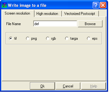
- Enter the name for the picture in the File name data entry box.
- Select which file format you would like to save the picture in by clicking in the circular selection button next to the file types. The options are .tif; .png; .rgb; .targa .eps.
- To specify which resolution you wish the picture to be saved click on the High resolution button at the top of the panel.
- Click the drop down arrow in the Resolution Increase data entry box and select which resolution you require the picture to be. Alternatively you can type the resolution you require into this box.
| NOTE: A quick way to save an image is to use the Quick Capture Graphics button on the toolbar which is described in the Picture Tips section of this manual. |
3.5.1.15 Preferences |
[ Bonds Preferences | Directories Preferences | Graphics Preferences | GUI Preferences | Gen Prefs | Image Preferences | Font Pref | Plot Preferences | Ribbon Preferences | Shell Preferences ]
Your ICM preferences can be changed by:
- Select File/Preferences.
| NOTE: There is a "Reset to Default" button in case you make any changes you are not happy with. |
3.5.1.15.1 Bonds Preferences |
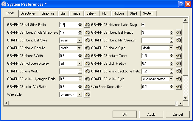
GRAPHICS.ballStickRatio - A default ratio of ball and stick radii. This ratio is applied when the styles are switched from the GUI xstick toolbar. Default (1.4)
GRAPHICS.hbondAngleSharpness determines how the strength depends on the D-H...A(lone pair) angle. The preference can be found the general Preferences menu Default (1.7)
GRAPHICS.hbond Ball Style even or telescopic
GRAPHICS.hbondWidth relative width of a displayed hbond .
GRAPHICS.hydrogenDisplay determines the default hydrogen display mode for the display command.
 GRAPHICS.hydrogenDisplay = "polar"
        1 = "all"   # all hydrogens are shown
        2 = "polar" <-- current choice  # polar displayed, the non-polar hidden
        3 = "none"  # no hydrogens are displayed
GRAPHICS.wire Width - relative width of wire Default (1)
GRAPHICS.xstick Hydrogen Ratio - Default (0.5)
GRAPHICS.xstick Vw Ratio - Default (0.6)
Wire Style - change the default wire style
GRAPHICS.distance Label Drag - enable distance label dragging
GRAPHICS.hbond Ball Period - Default (3)
GRAPHICS.hbondMinStrength - parameter determines the hbond strength threshold for hbond display. The strength value is between 0. and 2. By changing 1. to 0.2 you will see more weak hydrogen bonds. Default: (1).
GRAPHICS.hbondStyle - determines the style in which hydrogen bonds are displayed. Here hbond-Donor, Hydrogen, and hbond-Acceptor atoms will be referred to as D, H and A, respectively,
 GRAPHICS.hbondStyle = "dash"
        1 = "dash"      # the default choice. Just a line
        2 = "length"    # show the D-A distance in addition
        3 = "length and angle"  # show both the distance and the 180. - <D-H.. A> angle
GRAPHICS.hetatmZoom - The default ball and stick radii of a ligand can be different by the GRAPHICS.hetatmZoom factor. This makes a better ligand view since the ligand stands out from the surrounding protein atoms.
GRAPHICS.stickRadius - radius (in Angstroms) of a cylinder displayed as a part of stick or xstick graphical representation of a molecule. Individual (residue-wide) control of stick radii.
GRAPHICS.xstick Backbone Ratio - Default (1.2)
GRAPHICS.xstick Style - xstick style
wireBondSeparation the distance between two parallel lines representing a chemical double bond if wireStyle = "chemistry". Default (0.2 Angstroms).
3.5.1.15.2 Directories Preferences |
DIRECTORIES TAB:
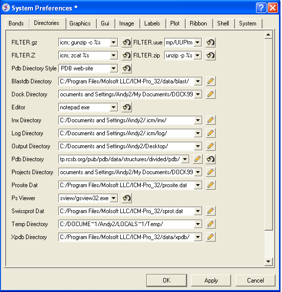
Within this tab you can select the default directories for:
FILTER.gz, FILTER.uue, FILTER.Z, Filter.zip allows you to read compressed files .gz, .uue, .Z, and, .zip files automatically leaving the compressed file intact.
PDB Directory Style - The style of your Protein Data Bank directory/directories. ICM will understand all of the listed styles, including distributions with compressed *.gz , *.bz2 and *.Z fil es
BlastDB Directory - return directory with Blast-formatted sequence files for ICM sequence searches.You can download Blast formatted databases from here ftp://ftp.ncbi.nih.gov/blast/db/
Dock Directory - Default directory for storing docking files.
Editor - Select a default text editor
Inx Directory - location of stored index (*.inx) files.
Log Directory - when you quit an icm-session, a _seslog.icm file is automatically stored. If the s_logDir variable is empty, it is stored to the s_userDir + "/log/" directory. However one can redirect it to the current working directory ( "." ) or any other directory.
Output Directory -
PDB Directory - directory containing the PDB database of 3D structures. These files can also be easily downloaded directly from the PDB site if the variables are set as in the example below. PDB distributions can exist in several styles (all files in the same directory, or divided etc.).
Projects Directory - Select the default location for storing ICM projects. Save your data in an ICM project. It is a convenient way of keeping all your structures, alignments, tables, docking results etc... in one place. A description on how to save an ICM project is described in the GUI Basics section of this manual.
Prosite Dat - location of the prosite.dat file a dictionary of protein sites and patterns, (Copyright by Amos Bairoch, Medical Biochemistry Department, University of Geneva, Switzerland).
Ps Viewer - Select a postscript viewer
Swissprot Dat - location of swissprot.dat file
Temp Directory - scratch directory for temporary files ( some montecarlo files will be saved there ).
XPDB Directory - Path to the ICM XPDB database of compact binary ICM objects which are annotated with the site information. The advantage of the XPDB database is the speed of reading and smaller size than PDB. XPDB entries are read about 80 times faster!
3.5.1.15.3 Graphics Preferences |
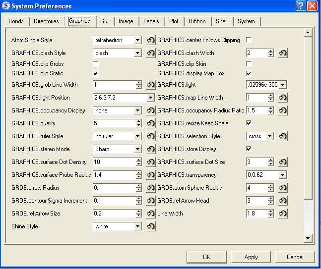
Atom Single Style - display style of isolated atoms in the wire mode.
   1. "tetrahedron"
   2. "cross"
   3. "dot"
GRAPHICS.clash Style - choose clash length, strain or length.
GRAPHICS.clip Grobs - enable grob clipping.
GRAPHICS.clip Static -
GRAPHICS.grobLineWidth - relative width of displayed lines of 3D meshes ( grobs ). Also affects the interatomic distance display.
GRAPHICS.lightPosition - X ,Y and Z posiion of the light source in the graphics window. The X and Y coordinates are usually slightly@@ beyond the [-1. 1] range where [-1.,1.] is the size of the window, and the Z position is perpendicular to the screen and is set to 2. (do not make it negative).
GRAPHICS.occupancyDisplay preference controlling if and how the partical or zero atom occupancies are displayed. The abnormal occupanices are shown as circles around atoms. These following values are allowed.
   1. = "none" # nothing is displayed
   2. = "circle" # a circle is displayed
   3. = "label" # a circle and a lable with the value (zero values are not shown)
GRAPHICS.quality - integer parameter controlling quality (density of graphical elements) of such representations as cpk, ball, stick, ribbon . Do not make it larger than about 20 or smaller than 1.
GRAPHICS.ruler Style - change ruler from center to side
GRAPHICS.stereoMode - 1. "up-and-down", 2. "line interleaved" 3. "in-a-window"
-
*a simple hardware stereo mode for workstations with a horizontal frame splitter.
*In the "up-and-down" mode a longer frame with two stereo images on top of each other is generated and the two halves are then superimposed with the splitter. This mode does not require anything from a graphics card, but does require a frame splitter. A frame splitter box was connected between a monitor and a graphics card output. This mode has an unpleasant side effect, the rest of the screen (beyond the OpenGl window) becomes stretched and the lower part of the screen is superimposed on the top half.
*The "line interleaved" mode can be used with a new type of frame splitter at the line level. In this case the odd lines from one stereo-image are interleaved with the even lines of another. The side-effect of this mode is that the intensity is reduced in half since at each moment one sees only one half of the lines. The splitter device for this mode can be purchased from Virex (www.virex.com). This mode produces a dark stereo image but is easily available (requires stereo goggles, e.g. from Virex).
*The "in-a-window" mode is used in SGI workstations and in a Linux workstation with an advanced graphics card supporting a quad graphics buffer. In this mode the hardware stereo regime applies only to an OpenGl window. This is the best mode but it requires an expensive graphics card (plus the stereo goggles).
GRAPHICS.surfaceDotDensity - Determines the number of dots per square Angstrom on the graphical solvent accessible surface.
GRAPHICS.surfaceProbeRadius - An increment to the van der Waals radii of atoms at thich the dotted atomic surface is calculated. It is used by the display surface command to display dotted van der Waals surface. If the GRAPHICS.surfaceProbeRadius is set to 1.4 the surface becames equivalent to the solvent accessible surface with a probe of 1.4A
GROB.arrowRadius - a real arrow radius in Angstoms used by the Grob( "ARROW", R_ ) function. Default: 0.5.
GROB.contourSigmaIncrement - a real increment in the sigma level used to re-contour an electron density map using the make grob m_eds add r_increment command. This parameter is used in the GUI when plus and minus are pressed.
GROB.relArrow Size - a real ratio of the arrow head radius to the arrow radius. This parameter is used by the Grob( "ARROW", R_ ) function. Default: 3.0.
shineStyle - defines how solid surfaces of cpk , skin and grobs reflect light. Possibilities:
   1. "white" <- default
   2. "color"
The first option gives a more shiny and greasy look.
GRAPHICS.center Follows Clipping - determine the function of center button.
GRAPHICS.clashWidth - relative width of a displayed clash .
GRAPHICS.clip Skin - enable skin clipping.
GRAPHICS.displayMapBox - controls if the bounding box of a map is displayed
GRAPHICS.light - a rarray of 13 elements between 0. and 1. which controls the main properties of lighting model in GL.
GRAPHICS.mapLineWidth - relative width of lines and dots of a displayed map.
GRAPHICS.occupancy Radius Ratio - preference controlling the radius of the partical or zero atom occupancies
GRAPHICS.resize Keep Scale
GRAPHICS.selectionStyle - preference for the style in which the graphical selection is shown. The preference may have the following values.
GRAPHIC.store Display - maintains representation and coloring for an object.
GRAPHICS.surfaceDotSize - Determines the size of the dot on the solvent accessible graphical surface.
GRAPHICS.transparency - Two parameters regulating the transparency of grobs.
GROB.atomSphereRadius - default radius (in Angstroms) which is used to select a patch on the surface of a grob.
GROB.relArrowHead - a real ratio of the arrow head radius to the arrow radius.
lineWidth - the real width of lines used to display the wire representation of chemical bonds.
3.5.1.15.4 GUI Preferences |
GUI TAB:
The options contained within the Preferences/Gui tab are described below.
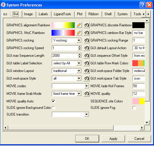
GRAPHICS.alignment Rainbow - This option controls how alignments are colored by default.
GRAPHICS.NtoC Rainbow - Controls the coloring of structural representation from the N-terminal to the C-terminal
GRAPHICS.rocking - Controls default rocking motion.
GRAPHICS.rocking Speed - Controls rocking or rotation speed.
GUI.auto Save Interval - Controls auto save period (minutes)
GUI.table Row Mark Colors - Controls colors used for marking tables.
GUI.workspaceTabStyle - Controls the style of ICM-object tabs created in the workspace panel of ICM GUI.
Movie.fade Nof Frames - Controls number of frames for the fade out option in screenshot movie making.
Movie.quality - Controls the resoltuion of the movie
SEQUENCE.site Colors - Controls coloring of squence sites.
SLIDE.ignore Fog - Fog representations can be ignored in slide preparation if desired.
GRAPHICS.discrete Rainbow -
GRAPHICS.rainbow Bar Style - determines if and where the color bar will appear after a molecule is colored by an array.
GRAPHICS.rocking Range - real value of rocking range.
GUI.auto Save - auto save on or off
GUI.max Sequence Length - maximum sequence length displayed in ICM
GUI.workspace Folder Style - Workspace folder style.
MOVIE.frame Grab Mode - with screenshot movie making you can choose either fixed frame time or real time.
Movie.quality Auto - with screenshot movie making you can allow ICM to control the movie resolution.
SLIDE.ignore Background Color - Ignore background color when you are making a slide.
3.5.1.15.5 General Preferences |
DISPLAY/GENERAL TAB:
Here is a summary of the important options in the DISPLAY/GENERAL Preferences Tab.
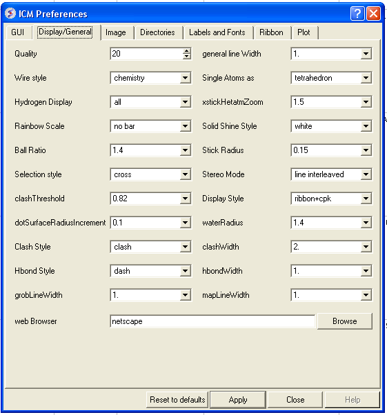
Quality - controls the quality (density of graphical elements) of such representations as cpk, ball, stick, ribbon . Do not make it larger than about 20 or smaller than 1. We recommend to make this parameter at least 15 if you want to make a high quality image. You can also increase the number of image resolution by making the image window 2,3,4 times larger (in the example below it is 2 times larger) than the displayed window.
Wire Style - Four different wire styles are available.
Hydrogen Display - Select whether you always want all hydorgens displayed or just-polar hydrogens or no hydrogens at all.
Rainbow Scale - determines if and where the color bar will appear after a molecule is colored by an array. Coloring by an array is one of the options of the display and color commands.
   1. = "left" <- default choice
   2. = "right"
   3. = "no text"
   4. = "no bar"
Ball Ratio - The ratio of ball and stick radii. This ratio is applied when the styles are switched to xstick from the GUI xstick toolbar.
Selection Style - Change the graphical display of your selections. Default is a green cross.
Clash Threshold - a clash is defined as an interatomic distance less than a sum of van der Waals radii of two atoms of interest multiplied by the clashThreshold parameter. For hydrogen bonded atoms, the distance threshold is additionally reduced by 20% . Default = 0.82
DotSurfaceRadiusIncrement - adius of a probe sphere used to display a dotted surface of a molecule. All van der Waals radii are expanded by this value. vwExpand=0 corresponds to the CPK surface, vwExpand=1.4 corresponds to the water-accessible surface. Be aware of the difference between the waterRadius and vwExpand parameters: waterRadius is used in
- show energy "sf"
- show [area|volume] skin
- display skin while vwExpand is used in
- show [area|volume] surface
- display surface
H Bond Style - How do you wish your H-Bonds to be displayed by default? Dashes, Bond Length, Bond Lenght and Angle.
grobLineWidth - relative width of displayed lines of 3D meshes ( grobs ). Also affects the interatomic distance display.
general line with - the real width of lines used to display the wire representation of chemical bonds. See also IMAGE.lineWidth parameter which controls line thickness in molecular images generated by the write postscript command, and the PLOT.lineWidth which controls the width for the plot command. Default (1.0)
single atom as - display style of isolated atoms in the wire mode.
1. "tetrahedron"
2. "cross"
3. "dot"
The size of the first two representation is controlled by the GRAPHICS.ballRadius parameter and the line width (especially important for the "dot" style) is controlled by the lineWidth parameter.
xstickhetatomzZoom - The default ball and stick radii of a ligand can be different. This makes a better ligand view since the ligand stands out from the surrounding protein atoms.
solid shine style - choose either white or color
Stick Radius - radius (in Angstroms) of a cylinder displayed as a part of stick or xstick graphical representation of a molecule. Individual (residue-wide) control of stick radii.
Stereo Mode - Select a default stereo mode
Display Style - A default display style can be chosen using a combination of styles.
Water Radius - radius of water sphere which is used to calculate an analytical molecular surface (referred to as skin) as well as the solvent-accessible surface (centers of water spheres).
clashWidth - relative width of a displayed clash.
hbondWidth - relative width of hydrogen bond display
mapLineWidth - relative width of lines and dots of a displayed map.
3.5.1.15.6 Image Preferences |
IMAGE TAB:
Here is a summary of the important options in the IMAGE Preferences Tab.
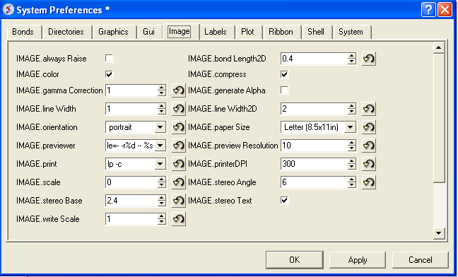
IMAGE.color - logical to save color or black_and_white ('bw') images.
IMAGE.gammaCorrection - real variable to to lighten or darken the image by changing the gamma parameter. A gamma value that is greater than 1.0 will lighten the printed picture, while a gamma value that is less that 1.0 will darken it.
IMAGE.lineWidth - this real parameter specifies the default line width for the postscript lines.
IMAGE.orientation - image orientation.
IMAGE.previewer - a string parameter to specify the external filter which creates a rough binary (pixmap) postscript preview and adds it to the header of the ICM-generated high resolution bitmap or vectorized postscript files saved by the write image postscript, and write postscript , respectively .
IMAGE.print - unix command for printer.
IMAGE.scale - real variable. If non zero, controls the image scale with respect to the screen image size.
IMAGE.stereoBase - real variable to define the stereo base (separation between two stereo panels) in the write image postscript and write postscript command.
IMAGE.writeScale - an integer parameter used to increase the image resolution in the Quick Image Write tool.
IMAGE.bondLength2D - real length of a chemical bond (in inches) in chemical 2D drawings upon the Copy Image command.
IMAGE.compress - logical to toggle simple lossless compression, standard for .tif files. This compression is required to be implemented in all TIFF-reading programs.
IMAGE.generateAlpha - logical to toggle generation of the alpha (opacity) channel for the SGI rgb, tif and png image files to make the pixels of the background color transparent.
IMAGE.lineWidth2D - integer thickness of bonds in chemical 2D drawing upon the Copy Image command. This is useful for cutting and pasting from ICM to external documnents.
IMAGE.paper Size - specify paper size.
IMAGE.previewResolution - integer resolution of the rough bitmap preview added to the vectorized postscript file in lines per inch.
IMAGE.printerDPI - this integer parameter the printer resolution in Dot Per Inch (DPI). Important for the write image postscript command.
IMAGE.stereoAngle - real variable to define stereo angle (relative rotation of two stereo images) in the write image postscript and write postscript command.
IMAGE.stereoText - logical to make text labels for only one panel or both panels of the stereo diagram.
3.5.1.15.7 Font Preferences |
LABEL FONT TAB:
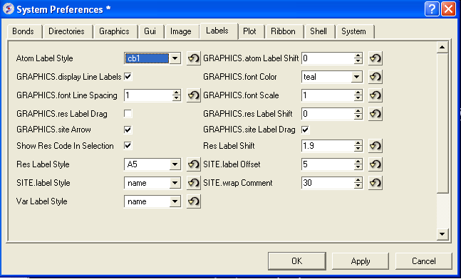
atomLabelStyle style of atom labels invoked by clicking on an the atom label button.
GRAPHICS.displayLineLabels - enables/disables the display of edge lengths (inter-point distances) of a grob generated with the Grob( "distance" .. ) function.
GRAPHICS.font Line Spacing - Change the spacing between lines in labels.
GRAPHICS.resLabelDrag - if yes, enables dragging of the displayed residue labels with the middle mouse button.
GRAPHICS. site Arrow - Highlight sites with an arrow yes or no.
Show Res Code In Selection - When you make a selection the icm selection language will be displayed when you right click on the selection.
Res Label Style - Default residue label style.
SITE.label Style - Default label sites style.
Var Label Style - Default label variable style.
GRAPHICS.atomLabelShift - a non-negative integer number of spaces preceding an atom label. This parameter is useful for displaying labels next to a solid representation,
GRAPHICS.fontColor - set font color
GRAPHICS.font Scale - set font size
GRAPHICS.site Label Shift - GRAPHICS.resLabelShift a non-negative integer number of spaces preceding a site label.
GRAPHICS. site Label Drag - if yes, enables dragging of the displayed site labels with the middle mouse button.
Res Label Shift - a non-negative integer number of spaces preceding a residue label. This parameter is useful for displaying residue labels next to a solid
SITE.labelOffset - (default 5. A) the real offset of the site label with respect to the residue label atom.
SITE.wrap Comment - Number of characters per comment line.
3.5.1.15.8 Plot Preferences |
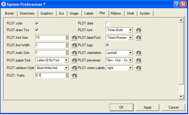
PLOT.color - logical to generate a color plot. Usually it does not make sense to switch it off because your b/w printer will interpret the color postscript just fine anyway.
PLOT.draw Tics logical yes or no
PLOT.fontSize real font size. Any reasonable number from 3. (1 mm, use a magnifying glass then) to 96.
PLOT.lineWidth - real line width for graphs (not the frame and tics)
PLOT.markSize - real mark size in points. Allowed mark types: line, cross, square, triangle, diamond, circle, star, dstar, bar, dot, SQUARE, TRIANGLE, DIAMOND, CIRCLE, STAR, DSTAR, BAR. Uppercase words indicate filled marks.
PLOT.paper Size - preference to specify plor paper size
PLOT.rainbowStyle - preference defining the color spectrum used by the plot area command.
PLOT.Yratio - real aspect ratio of the ICM plot frame. Using link option of the plot command is equivalent to setting this variable to 1.0. If PLOT.Yratio is set to 0. , the ratio will be set automatically to fill out the available box optimally.
[PLOT.date} - display date on plot
PLOT.font - preference for the title/legend font.
PLOT.labelFont - preference for the data point label font.
PLOT.logo - logical switch for the ICM-logo on the plot.
PLOT.orientation - preference for the plot orientation.
PLOT.previewer - command to local ps viewer
PLOT.seriesLabels - preference to indicate position of a series/color legend inside the plot frame.
3.5.1.15.9 Ribbon Preferences |
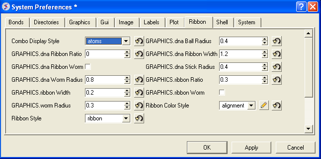
Combo Display Style - select ribbon-cpk, atoms, ribbon-ligand, chemical
GRAPHICS.dnaRibbonRatio - real ratio of depth to width for the DNA ribbon .
GRAPHICS.dnaRibbonWorm - logical which, if yes, makes the DNA backbone ribbon round, rather than rectangular. Default: no
GRAPHICS.dnaWormRadius - real radius of the worm representing bases in DNA ribbon .
GRAPHICS.ribbonWidth - real width of the protein ribbon .
GRAPHICS.wormRadius - radius of coiled segments (i.e. those where the secondary structure is marked as "_") of a polypeptide chain in ribbon representation. Default (0.3).
Ribbon Style - specifies default style when ribbon is displayed.
GRAPHICS.dnaBallRadius - DNA bases in ribbon representation are shown as balls controlled by this real parameter.
GRAPHICS.dnaRibbonWidth - real width (in Angstroms) of the DNA ribbon .
GRAPHICS.dnaStickRadius - real radius of the sticks representing bases in DNA ribbon .
GRAPHICS.ribbonRatio - real ratio of depth to width for the protein ribbon .
GRAPHICS.ribbonWorm - logical parameter, if yes, makes the ribbon round, rather than rectangular.
ribbonColorStyle -
- sets the ribbon coloring scheme.
1 = "type"	default. colors by secondary structure type or explicit color
2 = "NtoC"	colors each chain gradually blue-to-red from N- to C- (or from 5' to 3' for DNA)
3 = "alignment"	if there is an alignment linked to a protein, color gapped backbone regions gray
4 = "reliability"	3D gaussian averaging with selectSphereRadius of alignment strength in space
If ribbonColorStyle equals to 4, the conserved areas will be colored blue, while the most divergent will be red, and the intermediate conservation areas will be colored white. Example:
3.5.1.15.10 Shell Preferences |
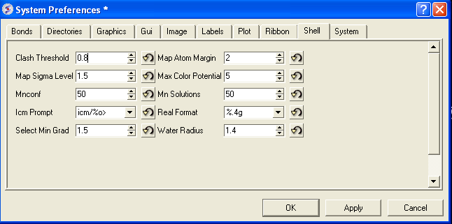
Clash Threshold - a clash is defined as an interatomic distance less than a sum of van der Waals radii of two atoms of interest multiplied by the clashThreshold parameter.
Map Sigma Level - (in Rmsd values over the mean value). Margin value used for making graphical objects contouring the 3D density map .
Mnconf - maximal number of conformations in the conformational stack . The stack stops growing after this number is achieved and starts replacing representative conformations with higher energy values by new conformations with superior energies, if the latter are found.
Icm Prompt - defines the ICM-prompt string.
Select Min Grad - default minimal gradient vector length for gradient atom selection ( a_//G). This parameter is also used by the montecarlo fast command, which requires a value of 2. to 10. for optimal performance.
Map Atom Margin - Margin in Angstoms around selected atoms. The margin is added to the positional boundaries to define a submap index box in the Map ( map_source , as_ ) function.
maxColorPotential - local electrostatic potential in kcal/e.u.charge units at which the surface element is colored by extreme red or extreme blue. All higher values will have the same color. This absolute scaling is convenient to develop a feeling of electrostatic properties of molecular surfaces.
mnSolutions - this parameter limits the number of hits retained by the program after a search.
Real Format - format of real numbers
Water Radius - radius of water sphere which is used to calculate an analytical molecular surface
system-preferences{FTP.createFile, FTP.proxy, GUI.max Nof Recent Files, GUI.splash Screen Image, HTTP.support Cookies, HTTP.user Agent, Beep, Max File Size Mb, USER.friends, USER.organization, FTP.keep File, GUI.enumberation Memory Limit, GUI.splash Screen Delay, HTTP.proxy, Http Read Style, Force Auto Bond Typing, USER.email, USER.full Name, USER.phone} h4-- System Preferences {System Preferences}
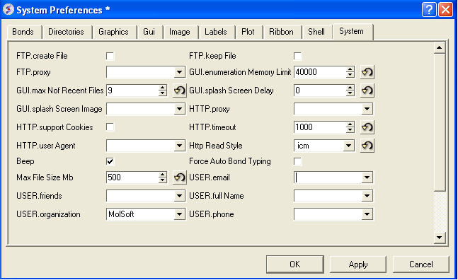
FTP.createFile -
FTP.proxy - string path to the proxy server for connections through firewall. Default: "" (empty string).
GUI.max Nof Recent Files - maximum number of recent files stored.
GUI.splash Screen Image - path to splash image displayed on startup
HTTP. support Cookies - http support cookies yes or no
HTTP.user Agent - client application used within a particular network protocol for www
Beep - warning beep yes or no
Max File Size Mb - Maximu file size in MegaBytes that can be loaded into ICM.
USER.friends
USER.organization
FTP.keep File - (default no ). If yes, the temporary file is kept in the s_tempDir directory. Otherwise the file is deleted.
GUI.enumberation Memory Limit - memory limit for enumeration operations.
GUI.splash Screen Delay
HTTP.proxy - string for HTTP server for connection through firewall
HTTP.timeout - timeout in seconds
Http Read Style icm or lynx
Force Auto Bond Typing - yes/no
USER.email, USER.full Name, USER.phone
3.5.1.16 Recent Files |
Recently viewed projects and files can be easily downloaded from the "Recent Files" option. To access this:
- Select File/Recent Files.
- Select the desired project by clicking on it once.
3.5.1.17 Recent PDB Codes |
Quickly retrieve and display PDB structures that have recently been viewed.
- Select File/Recent PDB Codes
- Select desired PDB code by clicking on it once and it will be loaded into the graphical display.
3.5.1.18 Quit |
Need to close down ICM - no problem. You do one of the following:
- Select File/Quit. ICM will quit without saving files.
- Save and Click X at the upper right corner of the ICM window.
- Type quit in the terminal window.
| NOTE: You may want to save the icm session as an ICM Project file before quiting. |
3.5.2 Edit Menu |
[ Delete | Delete All | Select All | Search in Workspace | Selection | Invert Selection | Clear Selection | Neighbor Selection | Undo | Redo | Restore | PDB Search | PDB Search by Field | PDB Search by Identity | PDB Search by Homology | PDB Search with External Sequence | Ligand Tools | Ligand Editor Preferences ]
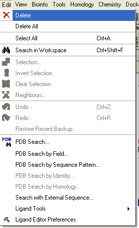
3.5.2.1 Delete |
This option will delete anything that is selected.
3.5.2.2 Delete All |
This option will delete everything e.g. sequences, structures, tables ... Use with care!
3.5.2.3 Select All |
This option will select everything e.g. sequences, structures, tables...
3.5.2.4 Search in Workspace |
This option allow you to search for a particular text in the workspace
3.5.2.5 Selection |
This option allows you to make a precise selection either by neighbors or specifying a particular atom or neighbor. Click on the tabs to jump between selection levels.
3.5.2.6 Invert Selection |
This option will select everything that is not currently selected.
3.5.2.7 Clear Selection |
This option will remove all selections. For more information on selections see the Making Selections Chapter.
3.5.2.8 Neighbor Selection |
This option will allow you to make a spherical selection.
The window will open as displayed as below:
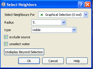
- Select the molecule you wish to select neighbors around. For example you can select a ligand in the ICM Workspace and then choose the Graphical Selection option in the "Select Neighbors For" dialog entry box. Or alternatively you can select the object by clicking on the drop down button next to the "Select Neighbors For" dialog entry box.
- Enter the radius in Angstroms for the neighbor selection. e.g. 5.
- Type - this option is important. This option relates to what is going to be selected. For example if you leave this option as visible and you only have ribbon representation displayed for your receptor (e.g. when selecting neighbors for a ligand) then only backbone atoms will be selected.
- visible - will select all atoms displayed within the radius selected.
- visible sidechains will select all visible side-chains - not backbone atoms.
- same_object_other_chains will select all atoms in other chains in the same object as the original selection.
- other objects will select atoms in objects other than the original selection.
- same object will select atoms in the same object as the original selection.
- all_objects will select atoms in all objects
- choose_from_list will allow you to select the object you wish to include in the neighbors selection.
- exclude source if checked will not include your original selection in the spherical selection.
- unselect water if checked will not select water molecules
- Undisplay Beyond Selection will only display the atoms selected.
3.5.2.9 Undo |
Due to the complexities of working in an internal coordinates environment not everything can be undone or redone. Certain things like coloring and representations can be undone or redone.
3.5.2.10 Redo |
Due to the complexities of working in an internal coordinates environment not everything can be undone or redone. Certain things like coloring and representations can be undone or redone.
3.5.2.11 Restore Recent Backup |
ICM periodically makes a backup of your ICM project. If for whatever reason you lose an ICM session and you want to load the backup for the file use:
Edit/Restore Recent Backup
3.5.2.12 PDB Search |
See PDB Search Tab
3.5.2.13 PDB Search by Field |
See PDB Search Tab
3.5.2.14 PDB Search by Identity |
See PDB Search Tab
3.5.2.15 PDB Search by Homology |
See PDB Search Tab
3.5.2.16 PDB Search with External Seqeuence |
See PDB Search Tab
3.5.2.17 Ligand Tools |
See the ligand editor section of the manual.
3.5.2.18 Ligand Editor Preferences |
See the ligand editor section of the manual.
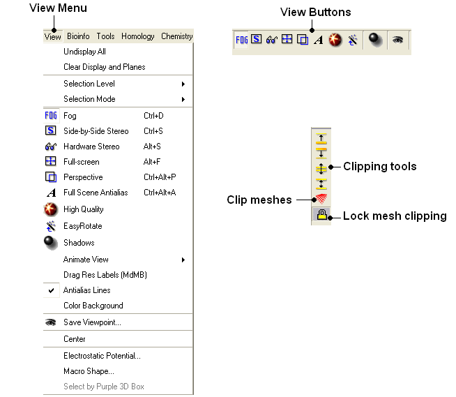
3.5.3 View Menu |
[ Undisplay All | Clear-Display-and-Planes | Selection Level | Selection Mode | Fog | Side-by-Side Stereo | Hardware Stereo | Full Screen | Perspective | Full Scene Antialias | High Quality | Easy Rotate | Shadows | Sketch Accents | Animate View | Drag Res Labels | Antialias Lines | Color Background | Save Viewpoint | Center | Electrostatic Potential | Macro Shape | Select by Purple 3D Box ]
3.5.3.1 Undisplay All |
To undisplay everything currently displayed in the graphical display
- View/Undisplay All
| Note For more details on displaying structures please see the GUI Overview chapter. |
3.5.3.2 Clear-Display-and-Planes |
To clear the display and planes
- View/Clear Display and Planes
| NOTE: For more details on planes please see the sections on clipping tools and mesh clipping. |
3.5.3.3 Selection Level |
There are four levels of selection - atom, residue, molecule and object. For more details on selections please see the Making Selections section.
3.5.3.4 Selection Mode |
There are four different ways to make selections - new, add, remove and toggle. For more details on selections please see the Making Selections section.
3.5.3.5 Fog |
Fog Toggle(Ctrl + D) : this feature creates a fog-like environment for your object, so that the part of your structure that is closer appears clear and the distant parts are faded as if they are in fog. The clipping planes control the point at which the fog begins.
- View/Fog
3.5.3.6 Side-by-Side Stereo |
Side-by-side stereo toggle(Ctrl + S) : this feature allows you to view your structure in 3D form without any 3D goggles.
- View/Side-by-Side Stereo
3.5.3.7 Hardware Stereo |
Hardware stereo toggle(Alt + S) - if you have 3D goggles and you wish to view your structure in 3D form, this feature will allow you to do so.
- View/Hardware Stereo
3.5.3.8 Full Screen |
Full screen toggleAlt_F - this makes your graphical display fill the entire screen. If you wish to exit this mode, press escape.
- View/Full Screen
3.5.3.9 Perspective |
Toggle perspective Ctrl_P this will add perspective to your structure, enhancing depth in the graphical display.
- View/Perspective
3.5.3.10 Full Scene Antialias |
Anti-aliasing is the technique of minimizing the distortion artifacts known as aliasing when representing a high-resolution signal at a lower resolution. Always use this option before making high resolution images.
- View/Full Scene Antialias
3.5.3.11 High Quality |
Toggle High Quality: this option will give your ICM object better resolution and higher quality. The change in quality is most visible at a high magnification. However, if your object is very large, this feature could slow down your program.
Always use this option before making high resolution images.
- View/High Quality
3.5.3.12 Easy Rotate |
Toggle easy rotation: this feature is necessary if your structure is very large or perhaps your computer cannot quickly rotate it. It will prevent your structure from fully loading each time you rotate it, therefore speeding up the process.
- View/Easy Rotate
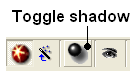
3.5.3.13 Shadows |
- View/Shadows
OR
-
select the shadow button shown below.
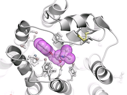
3.5.3.14 Sketch Accents |
To make images as shown below use:
- View/Sketch Accents
3.5.3.15 Animate View |
This tool is described in more detail in the Molecular Animations and Transitions section.
3.5.3.16 Drag Res Labels |
To change the location of your residue label:
- Select View/Drag res labels.
- If your mouse has a middle mouse button, then click on handle (as shown) of the label you wish to move, and drag it to your desired area.
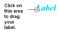
- If your mouse has no middle mouse button, then click on the Translation icon on the toolbar, and click on the handle (as shown) of the label you wish to move, and drag it to your desired area.
The +/- buttons on the side of the Residue and Atom buttons will shift the label. There are also other residue label move options available when you click and hold the residue label button. These options include Shift to Sidechain Tips, Shift to Calphas, and Restore Positions
3.5.3.17 Antialias Lines |
Use this option to activate antialias lines. It is recommended to leave this option selected.
- View/Antialias Lines
3.5.3.18 Color Background |
To change the background color
- View/Color Background
- Select a color from the panel and press OK.
This option is also in the more convenient display tab.
3.5.3.19 Save Viewpoint |
It is possible to store a current view using the button shown below.
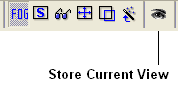
Click on the button and the current view will be stored so that you can view it later. A data entry box will be displayed asking you to name the view. All stored views can be found in the ICM workspace as shown below.
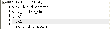
- Double click on the view in the ICM Workspace to display it.
A number of view display options are available by right clicking on the view in the ICM workspace as shown below.
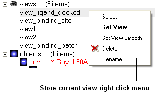
The option in the right click menu called "set view smooth" returns to the view slowly showing the trajectory between the original view and the current one.
3.5.3.20 Center |
To center on an object displayed in the graphical display
- Make a selection on the region on which you wish to center on.
- Tools/Center (or use the center button on the right hand-side of the graphical display).
3.5.3.21 Electrostatic potential |
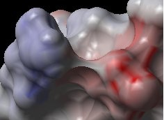
This option generates the skin representation of the molecular surface colored according to the electrostatic potential calculated by the REBEL method (hydrogen atoms are ignored). REBEL is a method to solve the Poisson equation for a molecule. REBEL is a powerful implementation of the boundary element method with analytical molecular surface as dielectric boundary. This method is fast (takes seconds for a protein) and accurate. REBEL stands for Rapid Exact-Boundary ELectrostatics. The energy calculated by this method consists of the Coulomb energy and the solvation energy
In order to color the skin of your molecule by electrostatic potential:
- Select View/Electrostatic potential.
- Enter the potential scale value. This is the local electrostatic potential in kcal/e.u.charge units at which the surface element is colored by extreme red or extreme blue. All higher values will have the same color. This absolute scaling is convenient to develop a feeling of electrostatic properties of molecular surfaces.
- Areas colored blue represent positive areas and red represents negative areas.
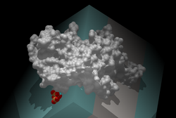
3.5.3.22 Macro Shape |
A macroshape allows easy viewing and manipulation of a structure. A macroshape representation is ideal for large structures which allows the user to easily identify important regions of the structure and facilitate the return to the 'standard' view of a particular molecule. The level of detail displayed in the macroshape can be controled by changing the number of harmonics, gridStep, and, contour level.
- View/Macro Shape
3.5.3.23 Select by Purple 3D Box |
[ bioinfo-menu ]
An alternative way to make a make-selection{selection} is to use the purple 3D box. To do this:
- Select the display tab and the purple box button
- View/ Select by Purple 3D Box
- The atoms contained within the purple box will be selected.
h3 -- Bioinfo Menu {Bioinfo Menu} __REQUIRES(ECB)
The tools in the Bioinfo Menu are described here
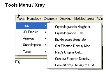
3.5.4 Tools Menu - Xray |
[ Crystallographic Neigbor | Crystallographic Cell | Biomolecule Generator | Get Electron Density Map | Map's Original cell | Contour Electron Density Map | Convert Xray Density to Grid ]
| Note: Click Next (top right hand corner) to navigate through this chapter. Headings are listed on the left hand side (web version) or by clicking the Contents button on the left-hand-side of the help window in the graphical user interface. |
3.5.4.1 Crystallographic Neighbor |
3.5.4.2 Crystallographic Cell |
3.5.4.3 Biomolecule Generator |
See Biomolecule
3.5.4.4 Get Electron Density Map |
3.5.4.5 Map's Original Cell |
3.5.4.6 Contour Electron Density Map |
See Contour Electron Density Map
3.5.4.7 Convert Xray Density to Grid |
See Convert Xray Density to Grid
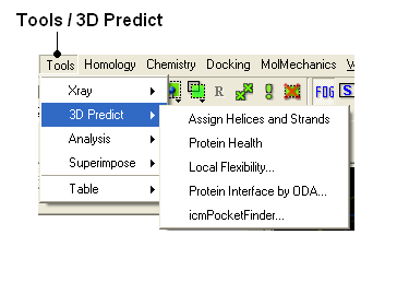
3.5.5 Tools Menu - 3D Predict |
[ Assign Helices and Strands | Protein Health | Local Flexibility | Protein Interface by ODA | icmPocketFinder ]
3.5.5.1 Assign Helices and Strands |
See Assign Helices and Strands
3.5.5.2 Protein Health |
See Protein Health
3.5.5.3 Local Flexibility |
3.5.5.4 Protein Interface by ODA |
See Predict Protein-Protein Interfaces
3.5.5.5 icmPocketFinder |
See Identify Ligand Binding Pockets
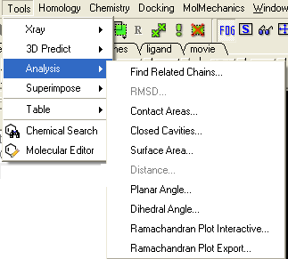
3.5.6 Tools Menu - Analysis |
[ Related Chains | RMSD | Contact Areas | Closed Cavities | Surface Area | Distance | Planar Angle | Dihedral Angle | Ramachandran Export ]
| Note: Click Next (top right hand corner) to navigate through this chapter. Headings are listed on the left hand side (web version) or by clicking the Contents button on the left-hand-side of the help window in the graphical user interface. |
3.5.6.1 Find Related Chains |
3.5.6.2 RMSD |
See Calculate RMSD
3.5.6.3 Contact Areas |
3.5.6.4 Closed Cavities |
See Closed Cavities
3.5.6.5 Surface Area |
See Surface Area
3.5.6.6 Distance |
3.5.6.7 Planar Angle |
3.5.6.8 Dihedral Angle |
h4 -- Ramachandran Plot Interactive {Ramachandran Plot} __REQUIRES(P)
3.5.6.9 Export Ramachandran Plot |
3.5.7 Tools Menu - Superimpose |
[ Display and Select Proteins for Superposition | Proteins by 3D | Multiple Proteins | Arrange as Grid ]
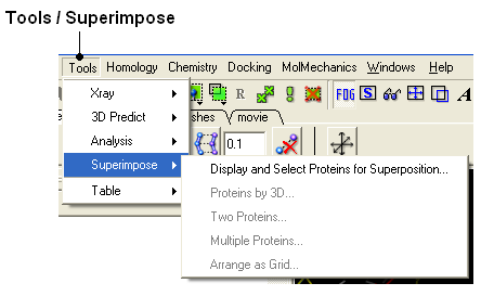
3.5.7.1 Display and Select Proteins for Superposition |
3.5.7.2 Proteins by 3D |
See Superimpose Proteins by 3D
3.5.7.3 Multiple Proteins |
See Superimpose Proteins by 3D
3.5.7.4 Arrange as Grid |
See Superimpose Proteins by 3D
3.5.8 Tools Menu - Extras |
[ Plot Function ]
3.5.8.1 Plot Function |
To plot a function:
- Tools/Extras/Plot Function
- Enter the Function(x) eg Sin(x)
- Enter the starting value of x (From).
- Enter the end point of x (To).
- Enter the number of points (N points).
- Click OK and your plot will be displayed next to a table of values for your function.
3.5.9 Tools Menu - Table |
[ Learn | Predict | Clustering | Table Merge | Columns | Append Rows ]
3.5.9.1 Build Prediction Model |
Learn and Predict tools are described here.
3.5.9.2 Predict |
Learn and Predict tools are described here.
3.5.9.3 Cluster Set |
This is described in the cluster section of the Working with Tables Chapter.
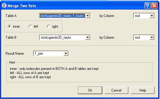
3.5.9.4 Merge Two Sets |
To merge two tables:
- Read the two tables into ICM.
- Tools/Table/Merge Two Sets
- Select the first table from the drop down list (Table A) and the column you wish to use to merge the table by.
- Select merge method 1. inner - only molecules present in BOTH A and B tables are kept; or 2. left ALL rows of A are kept ; or 3. right ALL rows of B are kept.
- Select the second table from the drop down list (Table B) and the column you wish to use to mergethe table by.
- Enter a name for the output table.
- Click OK and a new table will be displayed.
3.5.9.5 Add External Columns |
To add external columns to a table:
- Read at least two tables into ICM - the table you want to add to and the table you want to add the column from.
- Tools/Table/Add External Columns
- Enter the target table name and the column you wish to match each table by.
- Enter the source of the new column (Other table and column name)
- Choose to add "all the columns" from the source or "overwrite matching columns" or select the columns you want to add by selecting the "choose column" option.
3.5.9.6 Append Rows |
To append rows from one table to another one:
- Read at least two tables into ICM - the table you want to add to and the table you want to add the column from.
- Tools/Table/Append Rows
- Enter the name of the Target Table (where you will append).
- Enter the name of the Source Table (where you will append from).
3.5.10 Tools Menu - Chemical Search |
Chemical searching is described in the Chemistry chapter here.
3.5.11 Tools Menu - Molecular Editor |
The molecular editor is described in the Chemistry chapter here.
3.5.12 Homology Menu |
The options in this menu are described in the Homology Modeling Chapter.
3.5.13 Chemistry Menu |
The tools in the Chemistry menu are described here.
3.5.14 Docking Menu |
The tools in the Docking menu are described in the Docking chapter.
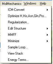
3.5.15 MolMechanics Menu |
[ ICM Convert | Optimize | Regularization | Impose Conformation | Edit Structure | MMFF | Minimize | Sample Loop | Normal Mode | Stack | GAMESS | Energy Terms ]
3.5.15.1 ICM Convert |
See Molecular Mechanics Chapter.
3.5.15.2 Optimize H,His,Asn,Gln,Pro |
See Molecular Mechanics Chapter.
3.5.15.3 Regularization |
See Molecular Mechanics Chapter.
3.5.15.4 Impose Conformation |
See Molecular Mechanics Chapter.
3.5.15.5 Edit Structure |
See Molecular Mechanics Chapter.
3.5.15.6 MMFF |
See Molecular Mechanics Chapter.
3.5.15.7 Minimize |
See Molecular Mechanics Chapter.
3.5.15.8 Sample Loop |
This option is described in the Loop Modeling section.
3.5.15.9 Generate Normal Mode Stack |
See Molecular Mechanics Chapter.
3.5.15.10 Stack |
See Molecular Mechanics Chapter.
3.5.15.11 GAMESS |
See Molecular Mechanics Chapter.
3.5.15.12 Energy Terms |
See Molecular Mechanics Chapter.
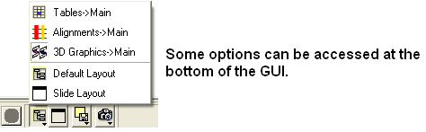
3.5.16 Windows Menu |
This menu allows you to choose the windows you wish to display. The windows which open automatically when you first open GUI are shown in the Default GUI section. Other windows can be displayed by selecting the windows menu. For example, if you have loaded a table but cannot see it in the GUI it may be because the Tables option in the window menu hasnt been selected.
To add or remove windows from the GUI display select the 'window menu'. Other windows not included in the default display such as tables and alignments can be added.
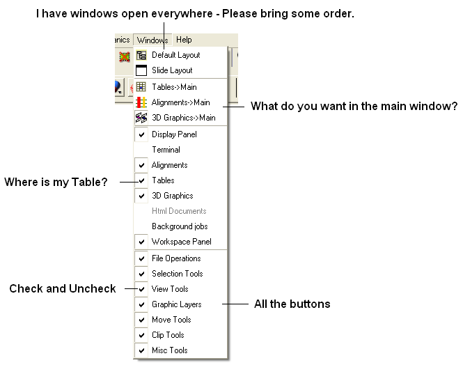
To return to the default display option select the 'Default layout' option in the windows menu.
OR
Click the default layout icon.
| Prev Measure Distance | Home Up | Next Tab Guide |